
")
Technology
Stereoscopic Technology
This area Stereoscopic Technology provides an overview of currently used techniques for two-channel image shooting (recording), framing (mounting) and playback (projection). The central element of all these processes is the independent handling of the left and right image field.
Our site is by no means exhaustive in the sense of a comprehensive technology overview but merely compares the currently most important and most widely used methods.
Just like in the flat picture photography, the complete processing chain consists of the three components shooting, image processing and playback.
Shooting, Production of Stereo Images
When shooting stereo images, two individual fields are produced, one for each eye. While a single image only gives an idea of the spatial perspective, a real perception of the third dimension can be reached with the binocular viewing of stereo images!
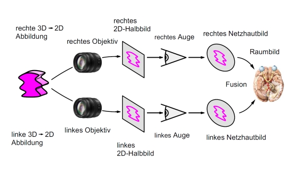
Figure 1: The path from the motive through the stereo capture to stereoscopic viewing
The easiest way to produce stereo images is to use a real stereo camera (3D camera). This is a camera with two equal lenses simultaneouslyrecording both fields with only one shutter release.
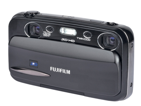
Figure 2: Genuine twin-lense stereo camera
The distance between the two lenses is called the stereo base, for natural-looking stereo it should be about 65mm (eye distance). Since currently on the market only very few industrially produced true stereo cameras are offered for sale, some alternatives have been established in the stereo scene:
→ Widely used are two identical cameras, mounted side by side and simultaneously triggered by remote control. This can be done with an external trigger, by manipulation the camera hardware or with an optimized firmware hack for stereo purposes (StereoData Maker).
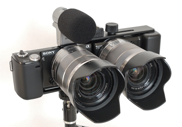
Figure 3: Stereo pair of two identical cameras
→ A Mirror-Rig is mounted by two individual cameras and a semi-transparent mirror so that both cameras can see the subject in the same manner, but do not interfere with each other. Using this technique, any small stereo bases are possible.
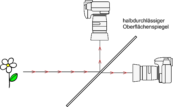
Figure 4: Mirror-Rig construction of two cameras and a semitransparent mirror surface
→ If the subject is completely static, the left and right shooting can also be carried out consecutively. For this, the camera is mounted on a sliding bar and moved between the two shots by the stereo base. Ideal for this technique are tabletop and macro photography, unsuitable on the other hand are landscapes as passing clouds or even in light wind moving leaves are bothersome when viewing.
| Real Stereo Camera | Team | Mirror-Rig | Shifting Technique | |
| Stereobase(typical values) | fixed, (3cm-7cm) |
variable (6cm-20cm) |
variable (0cm-10cm) |
variable (> 0cm) |
| Quality ofSynchronization | very good | depending on technology: poor to very good | depending on technology: poor to very good | – |
| Coupling of Distance and Focal Length | very good | depending on technology: not available to very good | generally not available | unnecessary |
| Need for post-processing: | ||||
| Stereo Window | generally necessary | urgently necessary | urgently necessary | urgently necessary |
| Geometric Errors | at modest claims sufficient | urgently necessary | urgently necessary | may possibly be sufficient |
| Chromatic Errors | generally not necessary | generally necessary | urgently necessary | generally not necessary |
Information: The SIG DGS Camera is currently developing a stereo camera on the basis of a Rasperry Pi.
Want to know more? Visit one of our regular meetings throughout Germany and discuss with us. Become a member of the DGS!
Photo credits: Figure 1,4: © Gerhard P. Herbig, Figure 2: Fujifilm FinePix Real 3D W3, © Fujifilm Corporation, Figure 3: SonyNEX 3D, ©Co van Ekeren
Framing, Mounting, Postprocessing
All three terms involve more or less the same: the cutting and mutual alignment of the two stereo fields. Only the correct mounting of two single stereo fields yields a wholesome and valuable stereo image.
While in the anlogue aera we talked about framing or slide framing, we prefere today in the digital age the terms mounting, stereo mounting or stereo alignment.
In commercial cinema area there has always been the "Postpro" (post-processing), which includes all subsequent image editing processes. For 3D film, this Postpro must now be extended at least to the stereoscopic requirements and the mutual alignment of the images.
The stereo image alignment is made up of two components,
1.) the geometric image correction, and
2.) the stereoscopic image cropping at the left and right edges of the two individual images.
1. The Geometric Image Correction
The geometric image correction has the goal to adjust all corresponding pixels in the left and right field to the same height. If this requirement is not fulfilled, stereoscopic experts speak of height errors. Causes of height errors can be: a simple vertical offset of the images, different sizes or rotations of the images, but also different trigger times of the cameras (synchronous errors).
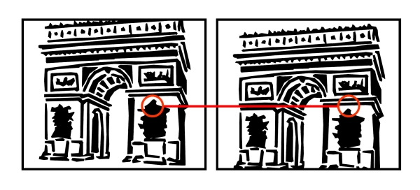
Figure 1: In a correctly mounted stereo image there must be only horizontal shifts of corresponding pixels. Here, the left image is clearly mounted too far upwards.
With the geometric image correction it is tried to equalize all height errors using all possible image manipulations as there are shifts, scalings, rotations, but also shears and keystone treatments.
2. The Stereoscopic Cropping
In a stereo projection the spatial image is perceived within an opening in an solid wall. This opening is called stereo window. By stereoscopic cropping of the left and right image fields, the position of the image space in relation to the stereo window is determined.
Whether an object can be seen behind the stereo window, in the stereo window or in front of the stereo window, is dependent entirely on the stereoscopic cropping and not from the shooting itself!
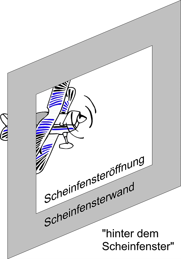
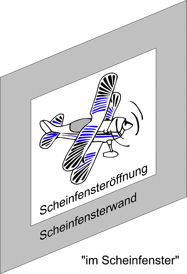
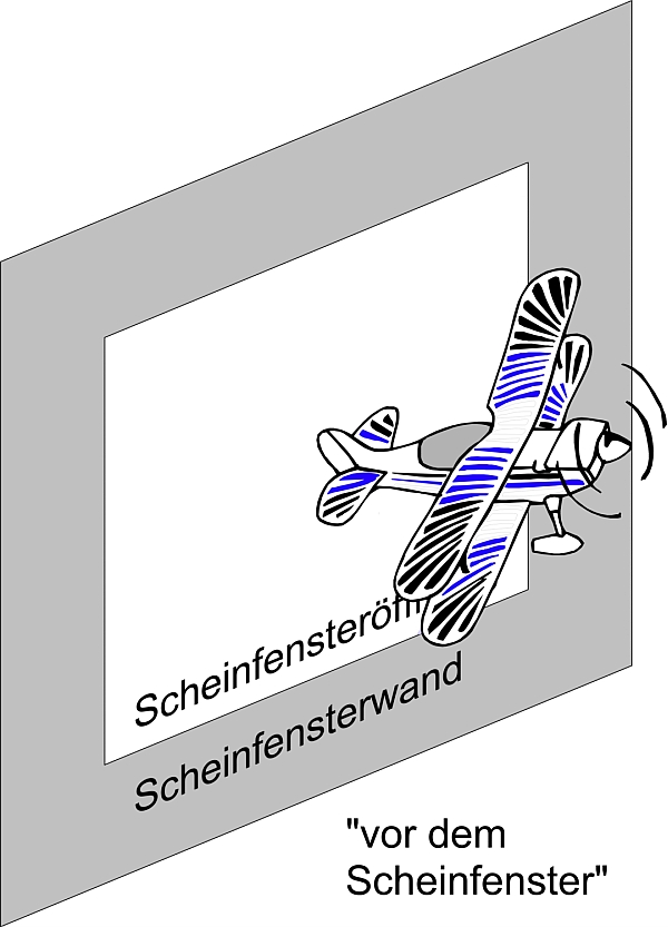
Figure 2 a,b,c: The same stereo image with three different stereo window mountings: behind the stereo window, in the stereo window and in front of the stereo window.
In deciding, where the motive is to be placed in relation to the stereo window, the term stereo window mounting has been established. Although naturally a creative act, this task can be taken over today by automatic mounting software.
3. Mounting Software
With appropriate software, both the geometric image correction as well as a proper stereo window setting can be carried out fully automatically. This is possible both for individual stereo images, complete directories of stereo images as well as for stereo video.
At this point, two programs shall be mentioned for these tasks:
The Stereophoto Maker is freeware and therefore especially suitable for entry into this wonderful world of stereoscopy. COSIMA represents COrrect Stereo IMAges and is a commercial software product, written by a member of the DGS. For the innovation of fully automatic stereo image correction, COSIMA was awarded by the DGS 2006 with the Deutsche Raumbildpreis.
Information: It is planned to work out the mathematical theory for stereo image matching in the SIG Stereobild- und Videokorrektur. This SIG has not yet begun.
Want to know more? Visit one of our regular meetings throughout Germany and discuss with us. Become a member of the DGS!
Photo credits: ©Gerhard P. Herbig
Playback, Presentation of Stereo Images
Any method which is able to exclusively show the left field to the left eye and the right field to the right eye is suitable for stereoscopic presentation. If you separate the different viewing methods according to the presentation medium, you get the following rough classification:
A. Methods for 2D Media (eg Prints)
B. Methods Showing the Image on a Monitor
C. Methods Using a Projector and a Screen
A1. Free Viewing
Side by side arranged stereo images can directly be look to without any additional aids up to an image size of about 6 cm. The DGS uses this method within its stereo journal and also on this website. Hereby the eyes look in parallel orientation to infinity, but must focus to vicinity. A small guide to learn this method can be found here.
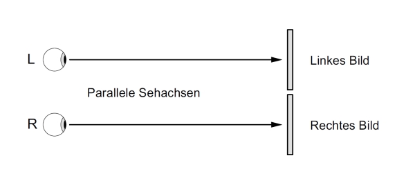
Figure 1: With free parallel viewing your left eye looks only to the left image and the right eye only to the right image.
A2. Stereo Viewer using Lenses (Lorgnette)
If additionally glasses with collecting lenses are used, the eyes no longer have to focus to the near area, but can relax and look into the distance. The focusing to the close is now taken over by the stereo glasses. This also fits much better to the parallel orientation of the eyes and therefore allows a relaxed vision to stereos. As a further development, for the Holmes Stereoscope prism lenses are used to increase the maximum image size to about 70 to 75 mm.
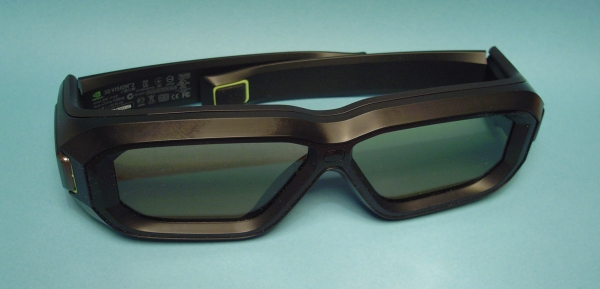
Figure 2: Using converging lenses in the glasses, we no longer have to focus to the near and can enjoy side-by-side printed stereo images without any effort.
A3. Crossed Eye Viewing
Since for human beings a divergent eye position is extremely uncomfortable (if at all possible), free stereo viewing doesn't allow greater images than about the eye distance. But if you interchange the left and right stereo field, much larger images can be viewed with some inward squint.
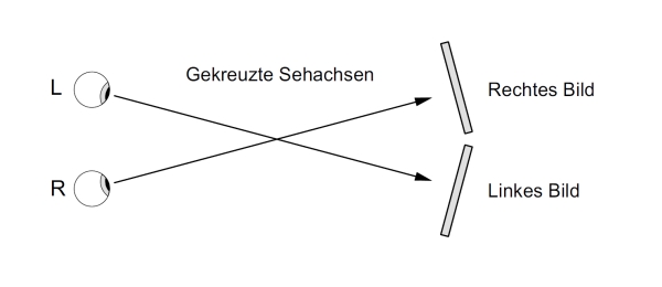
Figure 3: Who masters the cross-eyed viewing method, may look to large stereo images without glasses.
A4. KMQ
The inventors of the KMQ method (named after the inventors Christoph Koschnitzke, Reiner Mehnert and Peter Quick) have stacked the left and right field not stacked side by side but one above the other. Using prisms in the KMQ glasses direct the viewing beam path so that the two fields can be merged again to form a spatial image.
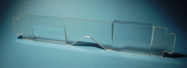
Figure 4: With using prism glasses, the stereo fields can be arranged one above the other.
A5. Anaglyphs
If (for example) coloring the left field into red and the right field into cyan and printing both fields superimposed, they can be separated afterwards again when viewing, if you wear glasses with corresponding color filters (anaglyph glasses). Since the colors are required now for field separation, the image itself can no longer be colored.
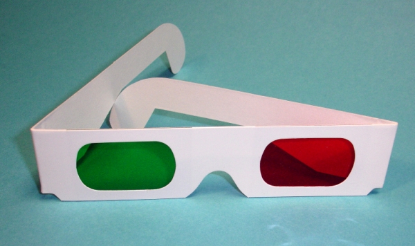
Figure 5: The red side of the spectacles lets only pass the light from the red (left) image field and the blue-green side lets only pass the blue-green light of the right image field.
B1. Polarized Monitor
3D monitors and 3D TVs with passive 3D technology work with circularly polarized light. This methode polarizes (eg) all even row numbers clockwise and all odd row numbers anti-clockwise. With appropriate polarized glasses then the left eye only see the even lines and the right eye only the odd. The correct preparation of the composed image (with interlaced lines) is either made by the player software or by the 3D TV itself.
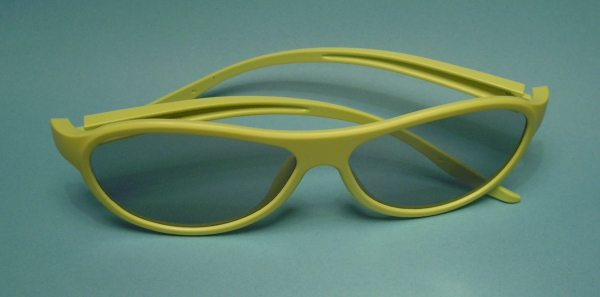
Figure 6: Passive polarized glasses with sleek modern design.
B2. Shutter Monitor
With shuttering, the left and right fields are alternately displayed. Since then the 3D glasses must be synchronized to the image changes; this technique is also called active.
Figure 7: Active shutter glasses from Nvidia®, the shutter eletronic is integrated into the temples.
B3. Mirror Box (Cobox)
Similar to the Camera Mirror Rig (see Technology - Shooting), a semi-transparent mirror and two normal computer monitors can be used to arranged a 3D viewing device. In appreciation to the Dutch 3D pioneer Co van Ekeren, this vision device is also called Cobox. For image separating the already existing polarization of the monitors is used, so that except the polarization glasses no further optical elements are necessary.
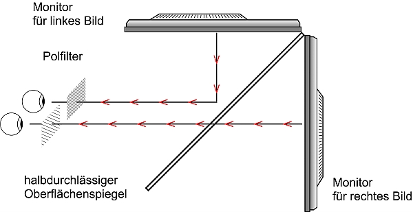
Figure 8: The beam path inside the Cobox. Many commercially available monitors already own from factory the correct polarization.
C1. Projection with polarized light
This method is applicable for analogue slides as well as for digital content in the same manner. The image of two projectors will be projected superimposed onto the screen. For separating of the image information, linearly or circularly polarized light can be used. To avoid depolarization (and intermixing of the two image information with each other), a metallized surface of the projection screen is required ("silver screen").
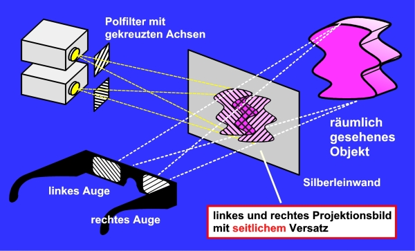
Figure 9: Arrangement with two beamers for stereo projection. For light separation, linearly polarized light is used here. This method ia also used for the DGS events.
C2. Shutter Projection
Both fields come from only one projector, alternatively for the left and right eye. The separation of the fields could be done again with shutter glasses (see above), which also alternately release the left and right viewing beam. Often the light is additionally polarized, and then for viewing inexpensive polarization glasses can be used.
C3. Infitec Projection
The German company Infitec® is the inventor of an image separation technology using interference filters. As things stand, the middle ranges of the 3 primary color spectrums are used for the right image field and the edges for the left one. Although colors are used for separation similar to anaglyph images, nevertheless differences in colors are virtually no longer detectable in the left and right image. The interference filter technology does not require a silver screen and can score with good light blockings and low transmission losses of the interference filter glasses. Interference technolgy has found worldwide distribution by the company Dolby3D®.
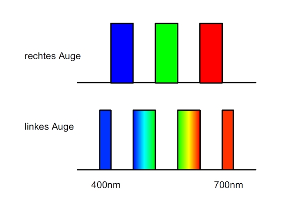 Image 10: Color separation with interference filter method according to Infitec®. In both fields all 3 basic colors are present.
Overview Table
| Advantages | Disadvantage | |
| Parallel Viewing |
|
|
| Parallel Viewing with Glasses |
|
|
| Crossed Eye Viewing |
|
|
| Anaglyphs |
|
|
| KMQ |
|
|
| Polarisation Monitor |
|
|
| Shutter Monitor |
|
|
| Mirror-Box (Cobox) |
|
|
| Polarisation Projection |
|
|
| Shutter Projection |
|
|
| Infitec Projection |
|
|
Information: The SIG Projection is focused on all technical aspects of polarization projection with 2 projectors.
Want to know more? Visit one of our regular meetings throughout Germany and discuss with us. Become a member of the DGS!
Photo credits: ©Gerhard P. Herbig